- Contact Us
- -
- Payment
- -
- 中文版
Knowledge Center · 2026-09-22 09:45:33 · 6 hits
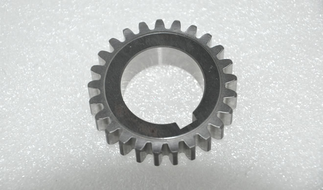
1. Definition & Function
What Backlash Is
Backlash is the small amount of clearance (play) between the non-driving tooth flanks of a meshing gear pair. Mechanically, it is the gap that lets one gear rotate slightly without immediately turning its mate. It is usually expressed as a linear value measured at the pitch circle (circumferential backlash) or normal to the tooth flank (normal backlash).
Why It Matters
Prevents jamming – Under thermal expansion, load deflection, or slight misalignment, a zero-clearance mesh would bind or seize. Backlash provides the breathing room that keeps the pair running free.
Absorbs manufacturing and assembly errors – Real gears carry tolerances on tooth thickness, center distance, and runout. A defined backlash budget tolerates these without forcing metal-to-metal interference.
Reduces wear and impact – A controlled gap lets a lubricating film form and avoids the wedging/impact that occurs when flanks are jammed tight; it also cushions reversal shock in reversing drives.
Caution on excess – Too much backlash causes positioning error, lost motion, noise, and tooth-face impact on reversal. The goal is a controlled, designed value, not "as much as possible."
2. Types & Principle
By Control Method
Fixed backlash – The clearance is established at the design and manufacturing stage (via tooth-thickness and center-distance tolerances) and cannot be changed in service. Suitable for the majority of standard drives.
Adjustable (compensated) backlash – The clearance can be set or trimmed in the field through shims, eccentric bearing housings, threaded adjustments, or spring-loaded split (anti-backlash) gears. Used where the operating condition or accuracy demand changes over time, or where near-zero lost motion is required.
By Magnitude / Class
Standard backlash – The clearance conforms to the applicable gear standard (e.g., AGMA, DIN, JIS) and suits general-purpose drives such as gearboxes and conveyors.
Precision (near-zero) backlash – The clearance is held extremely small, often via high-accuracy machining, matched pairing, and precise assembly, sometimes using anti-backlash (spring-loaded split) gears. Required for high-precision positioning, servo indexes, and measurement stages.
How It Is Created and Controlled
Backlash is generated mainly by (a) reducing tooth thickness relative to the theoretical value and/or (b) increasing the center distance. Fixed backlash is "built in" by the cut and the tolerance band; adjustable backlash is realized by mechanical means — shims under a bearing seat, an eccentric or threaded sleeve, or a spring-preloaded split gear that takes up the play. In precision systems, the assembly itself (matched pair, controlled center distance, bearing preload) sets the final value. As a rule of thumb for standard spur gears, increasing the center distance by Δa produces roughly j_t ≈ 2·Δa·tan α of circumferential backlash (α = pressure angle), which is why shimming the bearing seat is a common field adjustment.
3. Installation & Maintenance
Backlash (general)
Installation – Before fitting, verify the backlash value against the design specification (measure with a dial indicator or lead-wire crush test per the prescribed method). For adjustable types, set the value during installation and lock the adjustment.
Maintenance – Periodically re-check backlash; wear increases the gap over time. Keep the mesh lubricated to limit wear and monitor for abnormal noise or temperature that signals the clearance has drifted.
Precision / Near-Zero Backlash
Installation – For precision classes, the side clearance must be set exactly during assembly; control center distance and bearing preload carefully, and protect the setting from disturbance.
Maintenance – Beyond lubrication, keep the gears clean: dust, chips, or debris entering the mesh can locally block the flank and alter the effective clearance, degrading accuracy and accelerating wear.
4. Application Cases
Backlash Control in Practice
Industrial robot drivetrain – Adjustable-backlash gearing lets the backlash be fine-tuned so the robot keeps accurate motion even as it heats up in continuous operation; the setting compensates for thermal growth.
Automotive transmission / gearbox – Fixed-backlash gears, designed to a robust standard tolerance, ensure the unit never seizes across widely varying loads and temperatures, raising reliability and safety.
Precision machine tool – Near-zero-backlash gears, produced and assembled to high accuracy, hold stability and positioning precision at high spindle or axis speeds.
Aerospace drivetrain – Standard-but-tightly-controlled backlash, held by strict manufacturing tolerances, delivers reliability and durability under extreme environment and mission profiles.
5. How to Measure Backlash
###
6. Backlash and Positioning Accuracy: Worked Example
Backlash becomes "lost motion" at the output. Even a small mesh clearance can translate into a meaningful position error once reflected through the ratio and the working radius.
Example: a servo rotary table driven by a pinion (pitch radius r_p = 20 mm) and gear (pitch radius r_g = 80 mm, ratio 4:1). Measured circumferential backlash at the mesh j_t = 0.08 mm.
Angular lost motion at the output gear: θ = j_t / r_g = 0.08 / 80 = 0.001 rad ≈ 0.057°.
Linear lost motion at a load arm R = 150 mm: e = θ · R = 0.001 × 150 = 0.15 mm.
So a modest 0.08 mm of mesh backlash becomes 0.15 mm of dead band at the working radius — and on reversal the table can move that far before the load is re-engaged. This is exactly why precision stages specify near-zero-backlash or anti-backlash gears.
In a gear train, each stage's backlash reflects to the output through the intervening ratios; the total lost motion is the sum of every stage's angular backlash referenced to the output shaft. When specifying a positioning system, size the allowable backlash from the required final accuracy — not from the gear's catalog class alone.
Copyright © 2016-2025 Forrun (Guangdong) Industrial Technology Co., Ltd All Rights Reserved.