- Contact Us
- -
- Payment
- -
- 中文版
Knowledge Center · 2026-10-09 09:21:15 · 14 hits
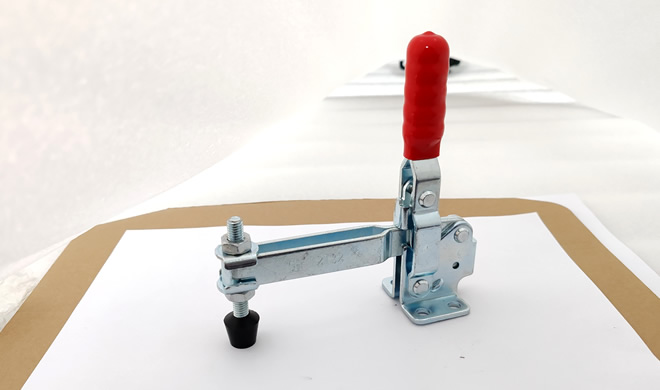
1. Definition and Working Principle
1.1 Definition
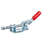
A toggle clamp is a workholding device that uses mechanical leverage or a cam (eccentric) mechanism to clamp and release quickly. It is used to locate and hold a workpiece steady during machining, assembly, and inspection, improving both efficiency and consistency.
1.2 Working Principle
Operating the handle drives a linkage that moves the clamp arm or hold-down spindle to clamp or release the part. A typical unit consists of a fixed base, a moving arm, a linkage, a handle, and a clamp arm. The defining traits are short stroke, high clamp force, and a stable lock.
2. Main Functions
2.1 Fast Positioning and Fixturing
A workpiece can be clamped and located in about 3 seconds, greatly reducing setup and changeover time.
Offers a clear efficiency advantage in batch production and line manufacturing.
2.2 Improved Machining Accuracy
Prevents part shift or vibration, keeping dimensional consistency across drilling, tapping, welding, and milling operations.
Repeatable clamping helps raise product yield.
2.3 Reduced Labor Effort
Bolt-type fixtures require repeated screwing; a toggle clamp locks with a light press of the handle.
Less operation time and physical burden improve operator comfort.
2.4 Safe Clamping
The clamp is self-locking, so it will not loosen automatically under external force while engaged.
Some models include a safety lock to prevent misoperation.
2.5 Flexible Mounting and Variety
| Type | Action | Typical use |
|---|---|---|
| Vertical (push-down) | Handle swings down; arm presses vertically | Most common; drilling, milling hold-down |
| Horizontal | Handle swings to the side; arm presses horizontally | Low-profile where vertical swing is blocked |
| Latch / pull | Hook draws parts together / locks a panel | Closing lids, covers, fixture doors |
| Push-pull | Pushes or pulls along the axis | Sliding gates, positioning stops |
These can be combined flexibly with welding tables, fixture plates, and line frames.
3. Typical Applications
3.1 Metalworking
Quick clamping and positioning at drilling, tapping, milling, and welding stations.
Common in custom tooling such as welding jigs, drill jigs, and assembly fixtures.
3.2 Electronics and Plastics
In electronic-component assembly and plastic-part machining, toggle clamps deliver high efficiency and holding stability.
3.3 Woodworking and Furniture
Used for panel holding, gluing, and cutting, with quick adjustment of clamp pressure and position.
Well suited to multi-step, linked workflows.
3.4 Automated Production Equipment
Integrated into clamping stations with pneumatic or electric actuation.
Frequently used in inspection devices, loading/positioning mechanisms, and automated fixtures.
3.5 Automotive and Sheet-Metal
Provides efficient clamping for vehicle structural-part machining and sheet-metal welding in fixture systems.
4. Key Purchasing Factors
4.1 Clamping Force
Select a model by the workpiece weight and the external forces generated during processing; common holding forces range from tens of kilograms up to over a ton.
4.2 Mounting-Form Match
Decide whether a vertical, horizontal, or latch type is needed, and confirm base hole spacing, mounting direction, and fit with the equipment or fixture.
4.3 Operating Frequency and Life
For high-cycle use, choose a reputable brand and check the handle's fatigue resistance and the mechanism's service life.
4.4 Automation Linkage
For automated fixtures, select clamps with an air-cylinder linkage or an electric-actuation interface.
5. Clamping Force and Safety Factor
A toggle clamp's rated clamp force is the hold-down force at the spindle tip, but the real load it must resist is the reverse (uplift) or cutting force acting on the part. Always apply a safety factor.
Required clamp force: F_req = (F_process + F_uplift) × SF
where F_process = cutting/machining force on the part, F_uplift = any force tending to lift the part, and SF = safety factor (typically 2–3 for manual fixturing; higher for dynamic or high-risk duty). The clamp must also resist sliding at the contact: the friction available = μ × F_clamp should exceed the tangential force.
Worked Example
A milling operation on an aluminum block generates a tangential cutting force F_process ≈ 800 N and a slight lift tendency F_uplift ≈ 200 N.
Choose SF = 2.5.
F_req = (800 + 200) × 2.5 = 2,500 N (≈ 255 kgf).
Select a clamp rated at ≥ 2,500 N hold-down (a common 250 kgf / ~2,450 N class vertical clamp fits, but use the next size up, e.g. 300 kgf class, for margin).
Verify sliding resistance: with μ ≈ 0.3 at the contact, available friction = 0.3 × 2,500 = 750 N > tangential 800 N? No — in this case raise clamp force or use a serrated/spindle tip to lift μ, since 750 N < 800 N of tangential force. This illustrates why both normal and tangential limits must be checked.
6. Manual vs Pneumatic Toggle Clamp
| Aspect | Manual | Pneumatic |
|---|---|---|
| Actuation | Hand lever | Air cylinder (often integrated) |
| Cycle speed | Limited by operator | Fast, consistent |
| Force consistency | Operator-dependent | Repeatable, pressure-controlled |
| Automation fit | Low (manual load) | High — PLC-controlled |
| Initial cost | Low | Higher (cylinder + valves) |
| Maintenance | Minimal | Seal / airline upkeep |
| Best for | Low/medium volume, jigs | High-volume, inline fixtures |
Rule of thumb: stay manual for low-to-medium volume and flexible jigs; move to pneumatic when cycle time, repeatability, or integration into an automated line justifies the cost.
7. Common Issues
| Issue | Likely cause | Corrective action |
|---|---|---|
| Clamp slips / part shifts | Undersized force; smooth contact | Use higher-rated clamp; serrated spindle tip |
| Handle won't lock (over-center fails) | Linkage worn / misaligned | Align linkage; replace worn pin/bush |
| Self-lock releases under vibration | Spring or latch weak | Use safety-lock model; add lock pin |
| Spindle marks the part | Hard tip on soft material | Use protective cap / plastic tip |
| Pneumatic clamp drifts | Air pressure drop / leak | Check supply; add lockout/regulator |
| Base loosens | Inadequate fastening | Use proper screws; thread-locker; torque |
Selection Checklist
Defined required clamping force (workpiece weight + process forces) with margin.
Chosen type (vertical / horizontal / latch / push-pull) for the motion and space.
Confirmed base hole spacing and mounting direction.
Matched duty cycle — high frequency → fatigue-rated, branded unit.
For automation, specified cylinder/electric interface.
Verified self-locking / safety-lock features for the risk level.
Checked both normal (hold-down) and tangential (sliding) limits.
Copyright © 2016-2025 Forrun (Guangdong) Industrial Technology Co., Ltd All Rights Reserved.