- Contact Us
- -
- Payment
- -
- 中文版
Knowledge Center · 2026-10-07 09:30:29 · 14 hits
1. Basic Structure and Function
1.1 Structural Features
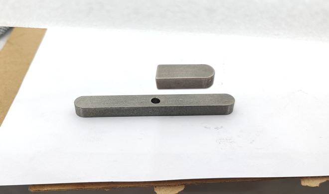
The cross-section is rectangular; the two flat faces seat against the shaft keyway and the hub keyway respectively.
Most types use a sliding fit, allowing the assembly to be dismantled and reassembled.
Torque is transmitted through side contact between the key and the keyway walls.
1.2 Main Functions
Provide coaxial drive between shaft and hub.
Constrain rotational freedom of the parts, ensuring consistent power transmission.
In some types (e.g., stop keys), also prevent axial movement.
2. Classification
2.1 By Installation Method
Type A — clearance-fit (free-assembly) key: The shaft and hub keyways use a clearance fit; easy to assemble and remove, suited to applications with frequent maintenance.
Type B — interference-fit key: Tightly fitted to the hub; installation requires light tapping or pressing; provides higher torque transmission and resists slippage.
Type C — tight (fastening) key: Essentially no clearance between key, shaft, and hub; suited to high-speed, heavy-load duty, though more complex to assemble.
Editor's note on GB coding: In the Chinese standard GB/T 1096, the letters A / B / C denote end shape, not fit class — A = round ends, B = square (flat) ends, C = one round end. The clearance/interference/tight classification above follows a vendor fit-based convention; when specifying to GB/T 1096, confirm whether "A/B/C" refers to end type or fit in the supplier's catalogue.
2.2 By Functional Feature
Ordinary flat key: Rectangular; the most common type.
Guide key: Allows axial movement; suited to sliding transmission.
Stop key: Has a block at the tail to prevent axial displacement.
Woodruff (half-round / segment) key: Used on special shaft profiles for positioning or light-load duty.
2.3 By Standard
| Standard | Scope |
|---|---|
| GB/T 1096 | General rectangular flat key |
| GB/T 879 | Round-head guide flat key |
| DIN 6885 | German parallel-key series |
| ISO 773 (formerly R773) | International general flat-key standard |
3. Tolerances and Fits
3.1 Tolerance Grades (example)
Width b: N9 (example range +0.05 to +0.075 mm — actual limits vary with nominal size).
Height h: h11.
Keyway: Recommended IT8–IT10.
Side contact between key and keyway should be tight; the top face does not carry load.
3.2 Fit Principles
The two side faces are the load-transmitting surfaces and should have minimal fit clearance.
The top face and keyway bottom must retain clearance to avoid interference — recommend ≥ 0.1 mm.
Use a locating/retaining plate or stop structure to prevent axial creep.
4. Selection and Applications
4.1 Selection Advice
Small/medium equipment: Prefer Type A for easy maintenance.
Large drive shafts: Recommend Type B or C for higher reliability.
High-precision equipment: Choose high-machining-accuracy DIN-standard keys.
Axial-load duty: Use a stop key or assist with a spring pin for positioning.
4.2 Typical Applications
Motor-to-reducer output connections.
Coupling and shaft mating assemblies.
Fixing of flywheels, pulleys, and sprockets.
Transmission shaft systems in automation equipment.
4.3 Common Nominal Dimensions (GB/T 1096 reference)
| Shaft dia. d (mm) | Key b × h (mm) |
|---|---|
| 6–8 | 2 × 2 |
| >10–12 | 4 × 4 |
| >17–22 | 6 × 6 |
| >22–30 | 8 × 7 |
| >30–38 | 10 × 8 |
| >38–44 | 12 × 8 |
| >44–50 | 14 × 9 |
| >50–58 | 16 × 10 |
| >58–65 | 18 × 11 |
| >65–75 | 20 × 12 |
| >75–85 | 22 × 14 |
| >85–95 | 25 × 14 |
| >95–110 | 28 × 16 |
| >110–130 | 32 × 18 |
*Representative subset; select the exact size from the standard table for the actual shaft diameter.
4.4 Key Length Series (GB/T 1096 reference)
Standard nominal lengths L (mm): 6, 8, 10, 12, 14, 16, 18, 20, 22, 25, 28, 32, 36, 40, 45, 50, 56, 63, 70, 80, 90, 100, 110, 125, 140, 160, 180, 200, 220, 250, 280, 320, 360, 400, 450, 500.
*Choose L so the working length l meets the strength requirement in Section 5; for Type A (round ends) l ≈ L − b, for Type B/C l ≈ L.
Selection Checklist
Confirm shaft diameter → pick nominal b × h from the standard. Choose end type (A/B/C) and fit class for the duty.
Verify side-fit tightness; keep top clearance ≥ 0.1 mm.
For axial restraint, specify a stop key or retaining plate.
Match the standard (GB / DIN / ISO) to the drawing requirement.
5. Strength Check (Bearing and Shear)
A flat key is checked for crushing (bearing) stress on its sides and for shear stress across its section.
Bearing stress: σ_p = 2T / (d · k · l)
Shear stress: τ = 2T / (d · b · l)
where T = transmitted torque, d = shaft diameter, b = key width, k ≈ 0.5h (contact height, or h − shaft-keyway-depth), and l = working length.
Worked Example
Shaft d = 50 mm; key 16 × 10 (b = 16, h = 10); length L = 80 mm, Type A → l = L − b = 64 mm; k ≈ 0.5 × 10 = 5 mm.
Torque T = 400 N·m = 400,000 N·mm.
σ_p = 2 × 400,000 / (50 × 5 × 64) = 50 MPa
τ = 2 × 400,000 / (50 × 16 × 64) = 15.6 MPa
For a typical steel key, allowable values are roughly [σ_p] ≈ 100–120 MPa (static) and [τ] ≈ 60 MPa — both checks pass with margin. Confirm allowable stresses against the actual key material specification.
6. Common Issues
| Issue | Likely cause | Corrective action |
|---|---|---|
| Key loosens / axial creep | No retaining plate; vibration | Add stop key or retaining plate; secure hub |
| Fretting on side faces | Micro-motion, poor side fit | Tighten side-fit tolerance; improve machining |
| Key shears off | Overload; undersized key | Increase b / h or length; re-check torque |
| Keyway edge chipping | Sharp corner, misalignment | Chamfer edges; align hub to shaft |
| Hard to assemble B/C type | Interference fit too tight | Use correct press/tap; verify hub bore size |
Copyright © 2016-2025 Forrun (Guangdong) Industrial Technology Co., Ltd All Rights Reserved.