- Contact Us
- -
- Payment
- -
- 中文版
Knowledge Center · 2026-10-16 09:45:30 · 20 hits
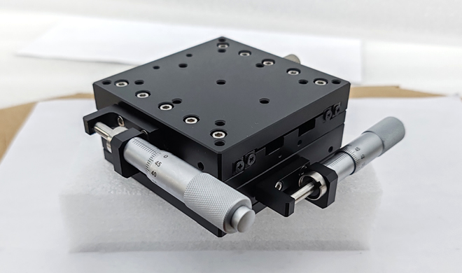
1. Structure and Components
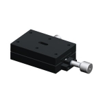
A crossed-roller stage is built from a slider (carriage), a guide rail, rollers, a cage (separator), and a base. Its core element is the crossed-roller guide pair: rollers are arranged at a 90° crossing angle within two precision-ground V-shaped raceways and held at equal pitch by the cage, forming a gap-free rolling support. This geometry gives the stage extremely high load rigidity and smooth, stable motion.
| Component | Function |
|---|---|
| Slider / carriage | Travels along the rail and carries the applied load |
| Guide rail (V-groove) | Precision-ground V-raceways that seat the rollers |
| Crossed rollers | Transmit load through rolling contact at 90° crossing |
| Cage / separator | Spaces rollers equally and retains them in the track |
| Base | Mounting foundation for the assembly |
2. Working Principle
The motion of a crossed-roller stage replaces sliding friction with rolling friction.
As the slider moves along the rail, the rollers alternately roll within the V-grooves and can absorb combined loads from vertical, horizontal, and moment (twisting) directions at the same time.
The crossed arrangement eliminates clearance, giving the stage high positioning accuracy and low frictional resistance.
Because the coefficient of friction is minute, the stage achieves light-start motion and stable low-speed travel — ideal for micro-displacement and precision positioning, with no stick-slip (crawling).
3. Key Performance Features
| Feature | Detail |
|---|---|
| High rigidity & load capacity | Multi-point roller contact; structurally stable under load |
| Low friction, no stick-slip | Enables continuous, smooth motion |
| High positioning accuracy | Repeatability error in the micron range |
| Compact form | Fits high-precision equipment in tight spaces |
| Easy maintenance | Long lubrication interval; simple to clean |
4. Typical Applications
| Field | Role of the crossed-roller stage |
|---|---|
| Optical inspection equipment | Lens focusing and alignment systems |
| Semiconductor manufacturing | Wafer handling and positioning |
| Precision measuring instruments | Stable micro-displacement control |
| Laser processing & microscopy | High-precision micro-positioning platforms |
| Automated assembly systems | Precision linear guide module |
Its value is greatest wherever synchronized, repeatable, low-vibration linear motion is required.
5. Selection and Installation Considerations
Define the required stroke, load (including moment loads), and accuracy grade.
Choose a preload class (clearance / light / medium preload) to balance rigidity against smoothness — higher preload raises rigidity but also friction.
Ensure mounting-surface flatness and parallelism to avoid binding and uneven wear.
Plan lubrication and contamination protection (covers, seals) per the duty environment.
Select cleanroom-compatible materials/lubricants when used in controlled environments.
6. Summary
With their high precision, high rigidity, and low friction, crossed-roller stages have become an indispensable positioning actuator in precision machinery and automation equipment. Proper selection, installation, and alignment significantly improve equipment accuracy and long-term stability.
7. Crossed-Roller vs. Crossed-Ball Stages
Both designs use 90°-crossed rolling elements, but the element shape changes the trade-offs.
| Criterion | Crossed-roller | Crossed-ball |
|---|---|---|
| Rolling element | Cylindrical roller | Ball |
| Contact type | Line contact | Point contact |
| Rigidity | Higher | Lower |
| Load capacity | Higher (same envelope) | Lower |
| Accuracy / repeatability | Excellent, especially under load | Excellent, best when light |
| Max speed | Moderate (low-speed micro-motion strong) | Higher (lower friction at speed) |
| Friction at start | Very low, no stick-slip | Very low |
| Cost | Higher | Lower |
Rule of thumb: choose crossed-roller for high-load, high-rigidity precision duty; choose crossed-ball for light-load, higher-speed, cost-sensitive stages.
8. Rated Load, Life, and the Effect of Preload
Rated life (linear travel form). For linear motion guides the rated life is expressed in kilometers of travel:
L = 50 · (C / P)^p (km)
where:
C = basic dynamic load rating (kN)
P = equivalent applied load (kN)
p = life exponent — 3 for ball elements, 10/3 (≈3.33) for roller elements
Worked example (crossed-roller stage): C = 10 kN, P = 2 kN, roller exponent p = 10/3.
(C/P) = 5; 5^(10/3) = 5^3 · 5^(1/3) ≈ 125 × 1.71 ≈ 213.8
L ≈ 50 × 213.8 ≈ 10,700 km rated travel (90% survival)
Preload and rigidity. Preload raises the stage's effective stiffness. Under Hertz contact, stiffness grows with the cube root of the total normal force:
K ∝ (F₀ + F)^(1/3)
where F₀ is the preload force and F the external load. Practical consequence: doubling the preload force raises rigidity by about 2^(1/3) ≈ 1.26× — but it also raises friction and shortens life, so preload should be the minimum that meets the rigidity target.
| Preload class | Rigidity | Friction | Life |
|---|---|---|---|
| Clearance | Lowest | Lowest | Longest |
| Light | Low–medium | Low | Long |
| Medium | Medium–high | Medium | Moderate |
| Heavy | Highest | Higher | Reduced |
Always apply the manufacturer's combined-load and preload-derating method for final sizing.
Copyright © 2016-2025 Forrun (Guangdong) Industrial Technology Co., Ltd All Rights Reserved.